A Minor Upgrade: Switch and Battery
Table of Contents
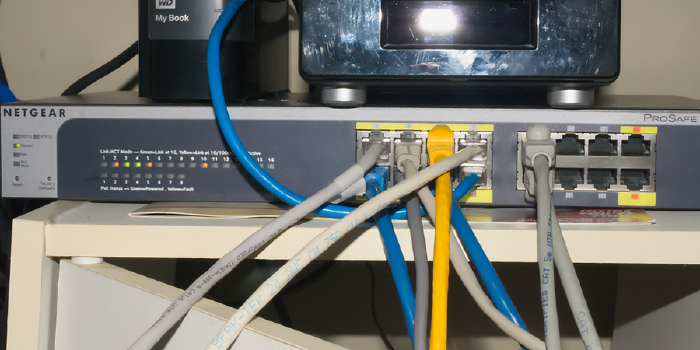
See also: managing to mildly destroy a network for 5 minutes while the switch has an anxious breakdown. Unfortunately, my reliable Dell PowerConnect switch has, well… it failed (kinda), and I was looking for an excuse to upgrade switches, so… I did. Admittedly, my impressions of Netgear kit aren’t the highest, but, hey, this switch is actually stupidly good for the price (I paid).
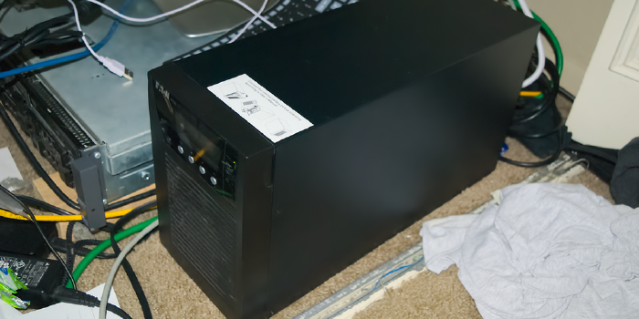
Oh, yeah, I also replaced the UPS since the entire network was offline anyways.
Now keep note that this and the next post (where I replaced the firewall) are all the same day and same general time. I’d link to it, but that circular dependency means that at least one of these two is going to link to a non-existent article, and an error of that magnitude would cause Hugo to explode into a supermassive black hole, destroying my site, the VM, the hypervisor, and eventually, my entire house, so please excuse me if I say literally just look forward one (or wait a day if this is the newest one).
The Battery
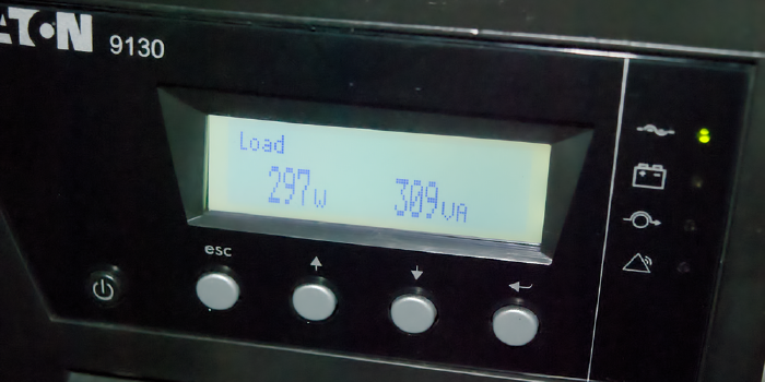
Backstory: this house is about to catch on fire. See, for a while now, I’ve been running my network off the outlets on one side of my room, which put the full 300-ish watt load on the same circuit as the living room.. with a completely separate home network, another R710 server, and, actually, a lot more stuff, as well as my gaming rig. Well with the new GPU that thing just got (let’s just say I jumped from a GTX 980 to a GTX 1080 Ti), we’re really pushing the limit of what a single 10 Amp circuit is capable of handling. Luckily, the outlets on the other side of my room are on a separate circuit and a separate 10A limit, one that’s barely utilized. So, I figure swapping outlets is as good a time as any to do some work. Part of this “work” involved fixing the issue where any time the power dipped, the hypervisor rebooted.
See, computer equipment like that is really sensitive to power fluctuations. That’s why, at some point, when we freed up a Geek Squad UPS (see also: “battery backup”), I just went ahead and shoved everything on that, since it’s capable of handling the load, and just about any UPS has AVR (Automatic Voltage Regulation), maybe that will help clean it up. And… it did, just not enough. That thing wasn’t capable of handling everything perfectly, and if the main power ever dipped and it went on battery, the switch over would cause enough of an anomaly to reboot the hypervisor. Luckily, we have a fix.
We found a really good deal on a 1500 VA Eaton 9130 UPS, a device actually meant to handle equipment this sensitive. (I’ll get to the numbers in a second.) They’re big, boxy (though there is a rack mountable version), and it’s now the noisiest piece of equipment in my room from the single always-on fan, but it has no trouble whatsoever here.
These units have a lot of connectivity options, like a USB interface, serial, and even a slot for a web-based management card (that’s a story for later), and that’s just for monitoring. There’s even a trip for emergency shutdown (aka “if these two pins aren’t connected anymore”), and said card can, depending, also take an environmental probe for humidity and temperature readings.
Even cooler fact: they have plugs to add extra batteries, which is a case about the size (okay, exactly the size) of the main unit, just with no faceplate and no display. You can add up to four (I think) extras in a daisy-chain fashion, if you have the extra space to spare, or just need the runtime.
A Word on VA
VA stands for volt-amps, which is a measure of “apparent power.” Note: this is going to get technical. Watts are the standard unit of power used in many fields, but we’re talking electricity here. The variable for watts in all equations shown will be P. Voltage is V, and Amperage is I. At first glance, the name volt-amp should roughly tell you the formula, V x I, which is also literally the equation for watts, P = V x I. This isn’t the case.
Wattage is real power, that is, the actual amount of energy required by the system. For normal everyday calculations, that’s all you really care about. With AC power and reactive loads, things get… tricky.
Put simply, reactive (inductive) loads cause the curve of amperage to not follow the curve of voltage, meaning one can be positive while the other is negative. This causes a lot of trigonometric weirdness which results in a number called Power Factor, or just pf. pf is a value between 0 and 1, where a perfect 1 means a non-reactive load, and a 0 is… oh dear. My network has an average pf of about 0.75 ish.
Volt-amps is just P / pf, meaning that a load of 100 watts with a pf of 0.8 is also a load of 125 VA. Batteries use VA not W because physics reasons, hence the odd choice of measurement.
The Switch
So, very quick intro, the switch is the piece of equipment in a network with a ton of Ethernet jacks that devices can plug into, the switch plays traffic cop, directing data to the right port based on the address given to it.
For a while I was using a Dell PowerConnect 2724, a 24 port managed switch. As far as equipment goes, it’s… old, and not without its quirks. Unmanaged (“dumb”) switches are pretty set–and–forget. You give it power, plug in the cables, and it starts switching. Done. Managed (“smart”) switches will also grab an IP address of their own and present some sort of management interface, usually a web interface, that can be used to configure, and, well, manage things.
The Dell switch can toggle between the two modes if you press a button with a paperclip and wait for it to reboot.
Doing so also clears it to factory default, nice.
From the interface you can set up link aggregation groups, VLANs, and check port statistics.
Well.. by default it statically assigns itself to 192.168.2.1, and waits for someone to connect and configure it.
After I got that UPS replaced and brought the network back up, the switch stopped responding.
Well, it was up, I could connect, I could even send it requests, but it would time out on giving me anything back.
Multiple resets later, it would respond to 192.168.2.1, but any attempt to change it, DHCP or otherwise, resulted in said time-out issue.
Okay, excuse to upgrade it is. Enter Netgear. This new switch only has 16 ports, not 24, but I’m only using 10, and this one has a lot of cool features that the other does not. Commencing list in 3… 2… 1…
Power over Ethernet (PoE)
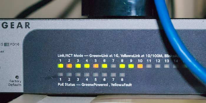
the first 8 ports (the yellow ones) are capable of delivering power to devices via the Power over Ethernet standard, and can even support higher draw devices (I think, and it’s called PoE+). This is useful for things like access points, which usually expect PoE instead of having a separate power adapter. The two devices can negotiate sending specifics, and then, in a manner not unlike XLR phantom power, the switch can supply up to ~15 or 30 watts of power. This is because gigabit and above Ethernet standards use differential signaling across the pairs. 10/100 Ethernet doesn’t do that, but also only uses 4 of the 8 available wires, leaving the rest free to just straight send voltage on.
Powered via PoE
In addition to providing PoE, the switch also can (but does not have to) be powered over PoE from ports 15 and 16, called the PD (Powered Device) ports. You either need a PoE+ or two regular PoE connections to give it enough juice, and then it can even provide PoE itself in a reduced capacity.
SNMP Monitoring
Putting aside my rant on SNMP for the time being,
there’s actually a lot of data you can get from a switch via SNMP.
Per-port traffic statistics, counters, all sorts of fun numbers to make graphs out of.
If you do know SNMP, there’s a standard MIB for this, the RMON-MIB.
DHCP Snooping
Enable this, enable MAC validation, and set a “trusted” port. This feature means the switch “listens in” on all DHCP conversations that pass through it (where machines get assigned IP addresses), and only DHCP offers from the “trusted” port(s) are allowed to get sent out. Once accepted, the switch notes this down, and will prevent that MAC from sending on a different IP address than the one assigned, and prevent that IP address from being used by a different MAC than what was assigned. In other words, this actually enforces the DHCP leases and reservations being handed out.
Flow Control
Also called 802.3x, if a device keeps filling its port’s buffer, the switch can send it a “pause” frame to inform the device to hush for a bit while it processes. A good use-case for this is if switches of different speeds are linked together, then the lower-speed one can regulate the sending from the higher-speed one to avoid overwhelming itself. If not enabled, once the buffer is full, traffic is just discarded.
Link Aggregation
This and VLANs are the main things the Dell switch can do, too. Link aggregation allows combining multiple physical ports into one logical port, thus adding the bandwidth of all links together. The most common method for this is called the Link Aggregation Control Protocol, or LACP, which is where a device that wants to aggregate informs an LACP-capable switch on what to aggregate. You as the admin and/or network engineer just need to tell the switch what ports to put in the aggregation group (LAG), and if it’s using LACP. The rest, namely, how traffic is split up between the interfaces, is left to the devices.
Practical example: By aggregating (or, “bonding”, or “teaming”, there’s multiple terms) both gigabit NICs from my NAS, there’s a total of 2 gigabit/sec throughput to that NAS (total, only 1 gig/sec is available to any one device).
VLANs
Virtual LANs (VLANs) are a way of splitting up a physical network into a group of access-controlled logical networks. These are identified by their VLAN ID, which can range from 1 (the default), to 4094. For example, most network traffic is on VLAN 1, but some traffic (say, from untrusted hosts) can be on VLAN 2, which the firewall is configured to block from talking to the IP address range assigned to VLAN 1. When configured correctly, for all intents and purposes of the end devices, they’re physically separate networks. Every port has a “PVID”, which is the VLAN ID that packets the switch receives belong to by default.
Ports may also be “members” of other VLANs, either “tagged” or “untagged”. Untagged packets mean “unmodified”, and the device at the other end receives just standard stuff. Tagged packets are an extra two bytes long that contain the VLAN ID, only really useful for “trunking,” sending multiple separate VLANs across the same port for the connected device to differentiate and use.
In a typical basic setup, every port’s only untagged membership is it’s PVID, and the only port with a tagged membership is that of the firewall, to enforce who can talk to who. Nowhere does any other device even know it’s on a VLAN since that information isn’t communicated, only handled internally by the switch. And with membership options set correctly, even if a device was attempting to look at other VLANs, the switch could discard that traffic since it’s not a member of the VLANs that it’s trying to use.
Spanning Tree Protocol
STP is a protocol that switches use to talk to other switches to prevent network loops from forming. If left up to a careless user, it’s possible to connect ports in such a way that there’s a loop. Such a loop will cause repeated forwardings until the packet’s TTL expires and it’s dropped, but get things just right (not that hard) and you’ll cause a complete network shutdown as the switches are now too busy processing packets on an endless loop to do anything useful.
STP creates a spanning tree — Think of this is a hierarchy of switches where each switch has one and only one path to other switches in the network. If a connection allows a loop to form and it’s of higher “cost” than another link, then that one becomes “blocked”, and will only be reinstated if the other “designated” link, as it’s called, fails.
Every few seconds a switch with STP enable will send out a packet called a BPDU (Bridge Protocol Data Unit), and this, if it hits another switch, will cause them to communicate, and eventually get all to agree on how to construct said tree.
There’s been a few developments over the years which I’ll get into in another post, but this switch supports both: RSTP and MSTP. RSTP is the rapid STP, and it’s just, well, faster. MSTP (Multiple) is an extension of RSTP. Whereas (R)STP work on physical links, MSTP takes into account VLANs, which can really get messed up if (R)STP is used without careful consideration.
IGMP
The Internet Protocol (version 4, I don’t even think about version 6) has the concept of three types of traffic, “unicast”, “multicast”, and “broadcast”. Unicast traffic means it’s supposed to go to one destination. Broadcast traffic means the entire network is supposed to receive it. Multicast means that some get it, some don’t, there’s multiple devices that can receive the same data. A specific IP address is used which identifies a “multicast group”, sent to the broadcast MAC address. If a devices wishes to participate in that group, the packet is received and parsed, else, it’s discarded.
Now, switches are left with an issue — multicast traffic is really hard to tell who actually wants it, and the best the switch can do is forward it to every single port. This is why we developed the Internet Group Management Protocol, or IGMP.
IGMP is an IPv4 specific thing (IPv6 has other methods), where a device will communicate “joins” and “leaves” to a switch to tell it what multicast traffic it actually cares about. If the switch is set to actually care, then when it receives multicast data, it will only send it to ports that it’s gotten an IGMP message saying that the device wants to be part of that group, making things much more efficient.
Layer 3 Switching
Most switches operate at layer 2, Ethernet. All they care about is the MAC (hardware) address of the Ethernet frame, and nothing else. Layer 3 switches are capable of reading the IP header and making decisions based on the source and destination IP addresses instead. A layer 4 switch can also decide on things like TCP or UDP port numbers, which gets pretty complicated, pretty quickly.
In effect, that means it’s also part router, able to forward frames to the right port just by knowing what goes where.
This allows, in combination with Access Control Lists, the ability to, at a basic level, handle cross-VLAN communication or simple IP / MAC based checks in the switch itself instead of forwarding to a firewall or other gateway to handle.
Yes, it’s entirely possible with an L3 switch to say, for example, that port 4 cannot ever talk to anything in the 192.168.5.0 subnet, for example, instead of having to send that to the upstream firewall and let another device have to process and evaluate everything.


